
Neware temperature chamber can be controlled on BTS 8.0 via TCP/IP communication, offering significant convenience for tests that require temperature variations across different cycles.
Here’s an example demonstrating the software setup with the 200L all-in-one chamber (MIHW-200-160CH).
1. Hardware Connection
1.1. Ethernet wire connection
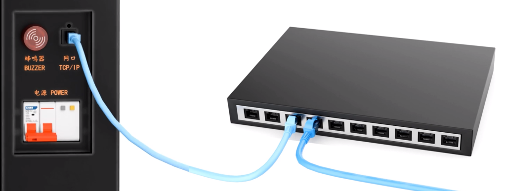
For a single all-in-one chamber, connect the Ethernet cable directly to the computer’s TCP/IP port.
For multiple chambers and testers, connect all Ethernet cables through a network switch.
2. Network Configuration
2.1 Record needed IP address
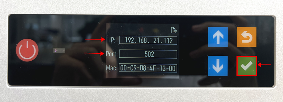
On the display screen, click the green button to view the chamber’s IP address and port.
In this instance, the chamber’s IP address is 192.168.21.112, and the port is 502.
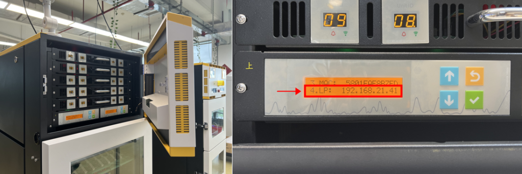
Here, the testers’ LP address is 192.168.21.41
2.2. Setting on the webpage
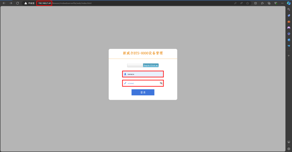
Open your browser and enter the IP address of the testers, which we recorded earlier as 192.168.21.41.
Username: neware
Password: xinwei
*Don’t forget to change the language to English.
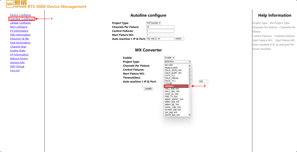
In the 【Autoline Configuration】 section, select the code 【M2WX64】, which is designated for chambers.
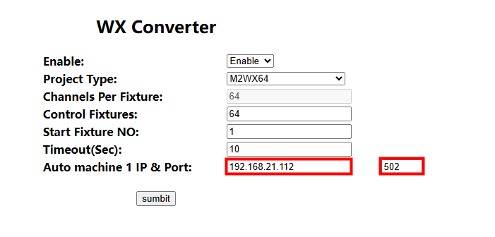
Now, enter the chamber’s IP address and port number that we recorded earlier. Then, click 【Submit】.
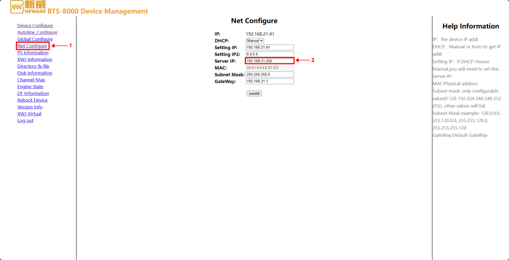
Next, go to 【Net Configure】 and enter the 【Server IP】.
The first three digits should remain the same as the chamber IP and tester IP, while the last digit should be set to 250.
2.3. Set up virtual temperature channels
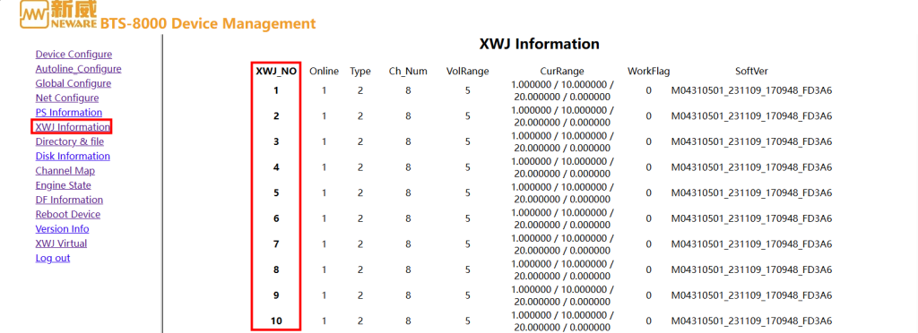
Click on 【XWJ Information】 to check the XWJ ID numbers.
Make sure to note these numbers, as you will need to avoid any duplicates in the later steps.
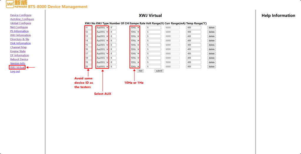
Click on 【XWJ Virtual】, add virtual auxiliary channels here.
Type in the ID number, note to avoid the same device ID numbers as the actual testers.
Select 【AuxXWJ】 for the 【XWJ type】.
Data record frequency can be either 1Hz or 10Hz (recommended) depending on your test requirement.
2.4. Reboot device
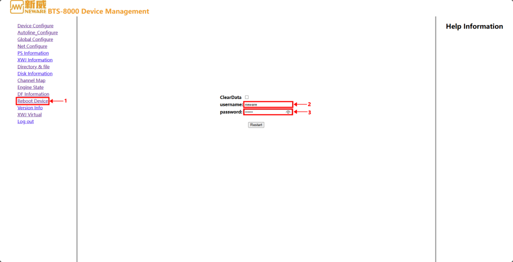
To save the changes we have made, we need to reboot the device.
User name: neware
Password: xinwei
3. BTS 8.1 settings
3.1. Reset mapping
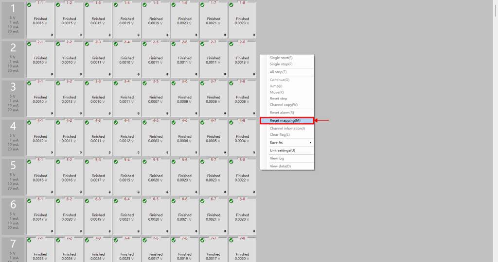
Log in to BTS 8.1.
Right-click and select “Reset mapping”.
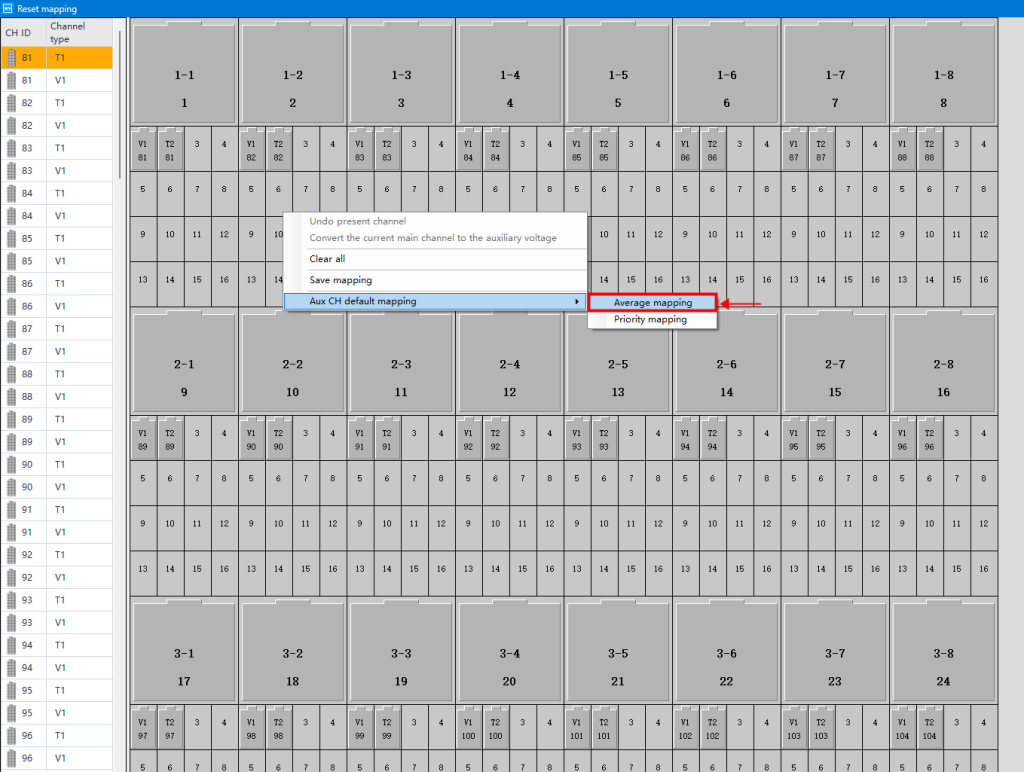
Evenly map the virtual auxiliary channels by selecting the 【average mapping】 option.
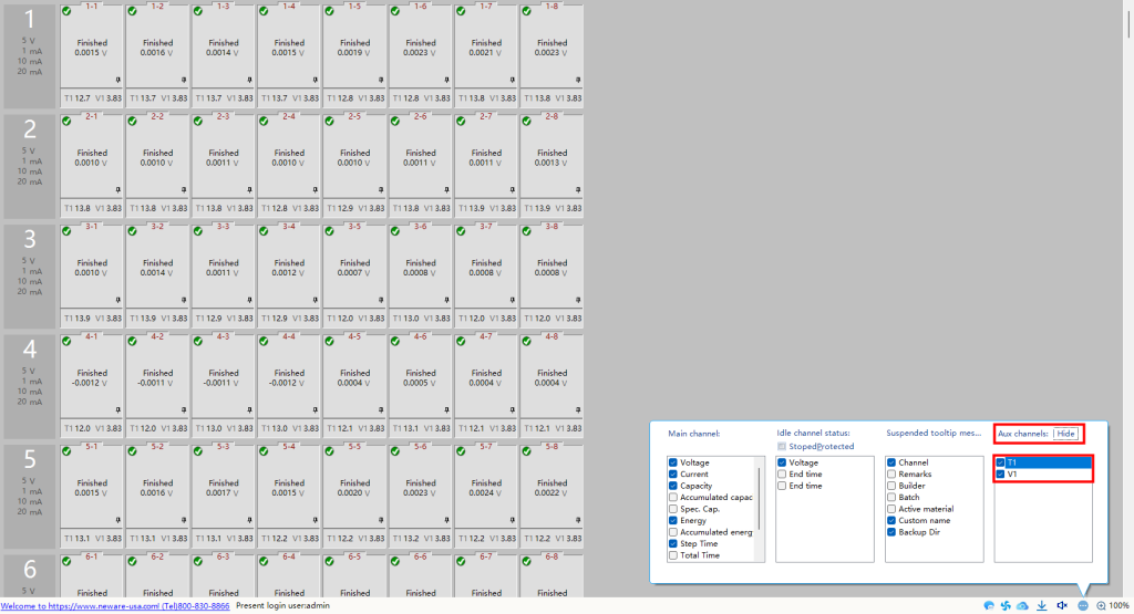
Modify on the display settings and you will see the virtual temperature readings.
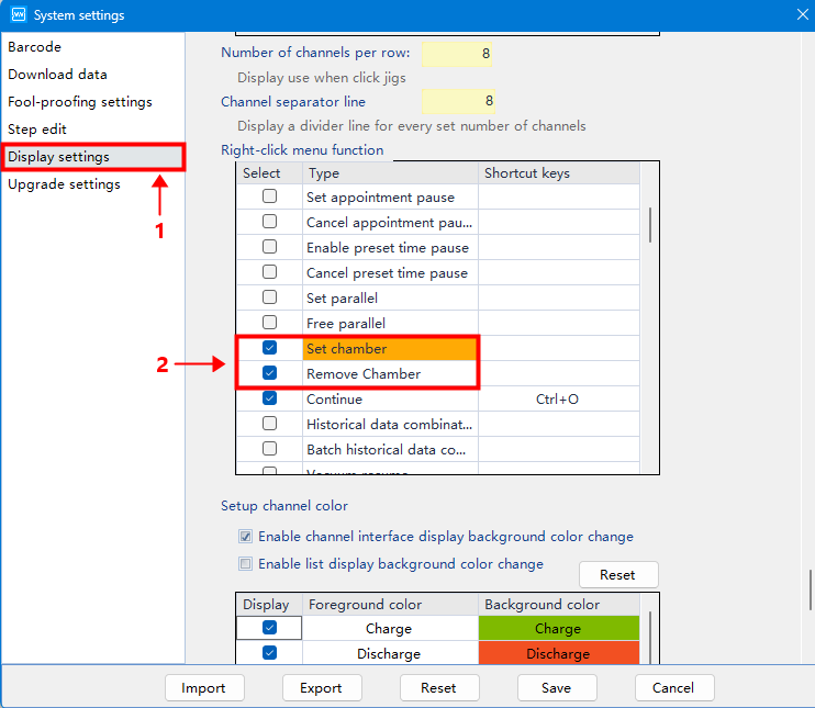
In the system setting, find the 【Right-click menu function】 under 【Display settings】.
Select both 【Set chamber】 and 【Remove chamber】, then save the changes.
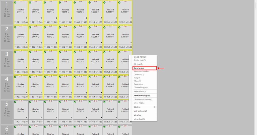
Select all the relevant channels within this temperature zone, and then click on 【Set Chamber】.
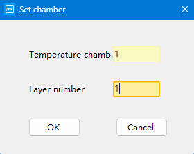
For single-zone temperature chambers, enter “1” in both columns.
For double-zone temperature chambers, specify the differences in the layer number accordingly.
4. Set work steps
4.1. Temperature control step
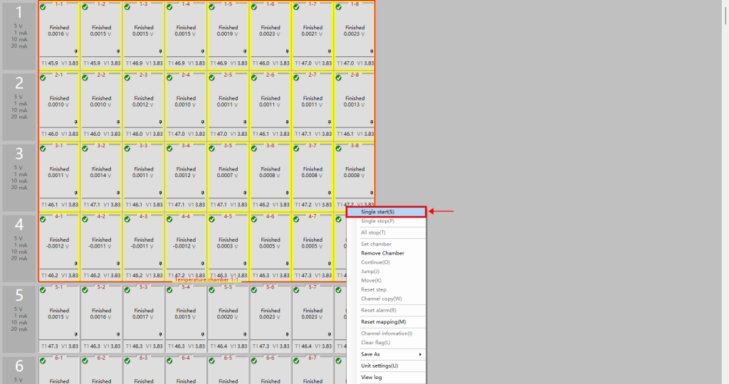
The temperature chamber is now assigned to the test channels.
Right-click and select “Single Start(s)” to configure the work steps.
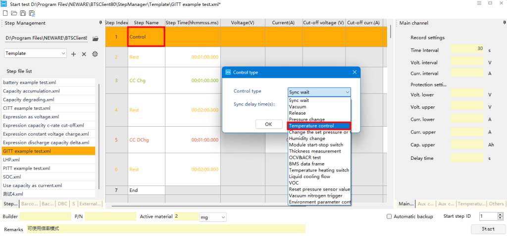
Select the 【Control】 work step.
Double-click on the row, and choose the control type of 【Temperature control】.
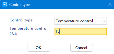
Set your desired temperature according to your testing requirements.
4.2. Complete your work steps, and then start running the test.