
For BTS6000 testers debugging communication and parameter settings.
*Please note: the connection for the IGBT station is different from the connection for the cell and module tester. Both methods are mentioned below. If you are not sure about your tester model type, please contact your sales rep.
Download: BTS6000_Debugging_Software
For BTS6000-IG station
1. The composition of the debugging cable
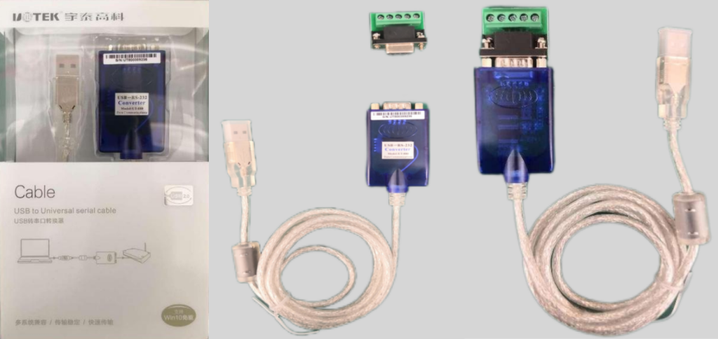
(1) A RS232 to USB cable. Product code: A306-USB-RS232-UT880. We’ll call it “UT880” in later content.
(2) A 5-position DB9 female elbow connector. Product code: A209-DB9-5.
(3) Three 0.5mm² wires, the colors should be red, black, green-mix-yellow. The length of the wire is determined by the distance from the customer’s equipment to the debugging computer.
* Note: Items 1 & 2 are included in the order package. Item 3 should be prepared by the clients themselves.
2. Cable connection
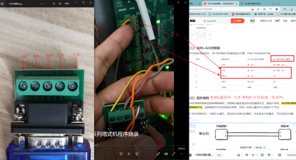
(1) The signals of the DB9 connector are GND, RXD-, RXD+, T/R-, T/R+ (from left to right).
(2) Connect UT880 cable to DB9 connector.
(3) Insert red (or orange) cable to port “T/R-“.
(4) Insert black (or grey) cable to port “RXD+”.
(5) Inset green-mix-yellow cable to port “GND”.
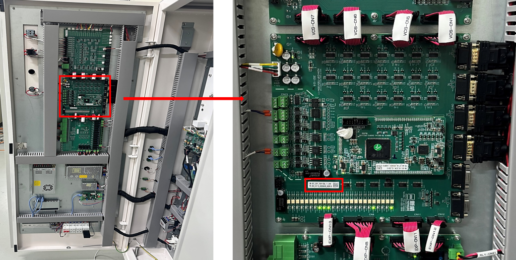
Find the 2nd PCB board which is located at the left-front door of the IGBT station.
Check product code on the sticker: B01-EXP-xxxVxxxA-1.1
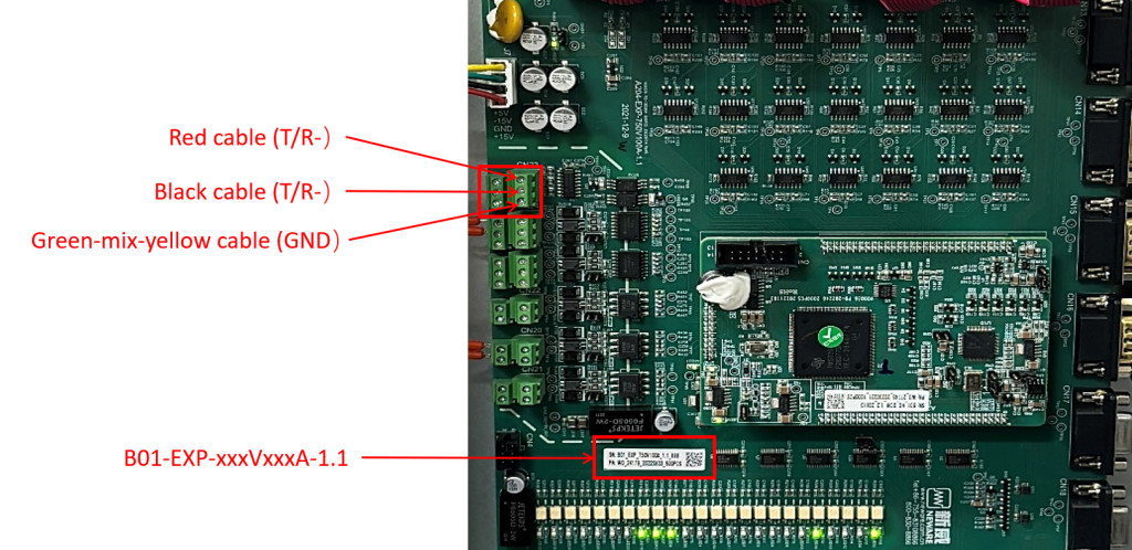
Find the first terminal on the EXP board.
(1) Connect the red (or orange) cable to port “T/R-“.
(2) Connect the black (or grey) cable to port “RXD+”.
(3) Connect the green-mix-yellow cable to port “GND”.
Plug the USB terminal into the host computer. And you are good to go.
For BTS6000 cell & module testing
1. The composition and connection
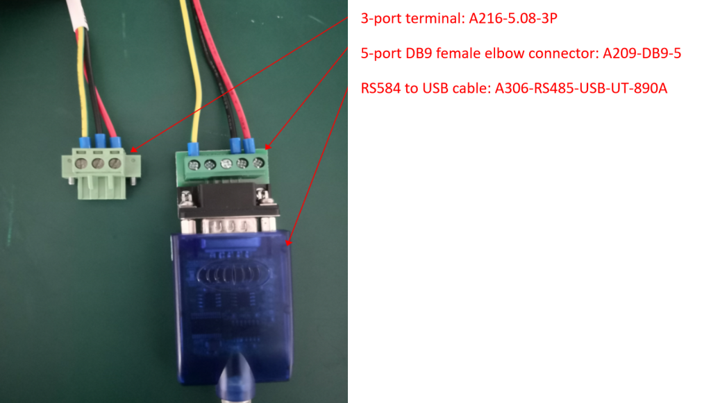
(1) A RS485 to USB cable. Product code: A306-RS485-USB-UT-890A. We’ll call it “UT890A” in later content.
(2) A 5-position DB9 female elbow connector. Product code: A209-DB9-5.
(3) A 3-port terminal. Product code: A216-5.08-3P.
(4) Three 0.5mm² wires, the colors should be red, black, green-mix-yellow. The length of the wire is determined by the distance from the customer’s equipment to the debugging computer.
* Note: Items 1 & 2 &3 are included in the order package. Item 4 should be prepared by the clients themselves.
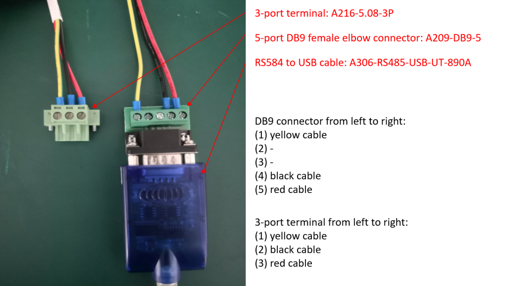
Connect the cables as shown in the image above.
2. Connect to tester
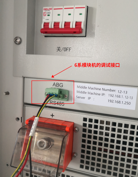
Plug the 3-port terminal to the RS-485 port on the tester.
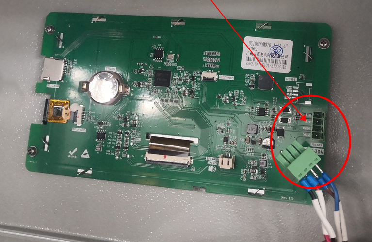
Open the tester’s side door, and unplug the touch screen’s signal cable. Good to go.
* Note: remember to plug the signal cable back after debugging.