
The BTS6000 module tester operates within a voltage range of 20V to 200V and utilizes a 3-phase-5-wire connection.
Here’s a guide for BTS6000 set up, with a focus on our module testers.
Recommended computer configuration:
- CPU processor is I5 or above
- Memory capacity is greater than or equal to 8GB
- Hard disk space is not less than 1TB
- Recommended computer operating system: win7, 10, 11 (64-bit).
- If you’re setting up a new computer that requires memory partitioning, ensure the software installation disk (separate from the system disk) has at least 400GB of available space.
1. BTS6000 Safty requirement
1.1 Qualified operator
To guarantee the safety of both personnel and equipment during installation, only professional electricians and qualified personnel should handle the transportation and installation of this product.
1.2 Environmental requirement
To ensure the proper and safe operation of the equipment, please verify that your site meets the following requirements:
- The equipment must be installed on a flame-retardant surface supported by a channel-steel structure. Additionally, the ground should be level and possess sufficient load-bearing capacity to support the installed equipment.
- No direct sunlight and good ventilation.
- Temperature -10~40°C, no dramatic temperature changes.
- Relative humidity ≤ 70% RH, no water vapor condensation.
- Altitude less than 2000 meters.
- No high concentration of dust, producible gas, or corrosive gas.
- During installation, it is essential to maintain an appropriate gap between the equipment and solid objects (such as walls) to ensure adequate ventilation and safe evacuation in case of an emergency. A minimum of one person’s space (≥600mm) should be left around the equipment. Additionally, there must be sufficient clearance above the equipment for ventilation, operation, and maintenance, typically at least 500mm.
2. Power cable connection
2.1 Cable requirements
Neware will supply you with the appropriate power cables. However, if you choose to use your own cables on-site or make adjustments in the future, please adhere to the following requirements:
- The chosen cable must possess adequate current-carrying capacity. This capacity is influenced by several factors, including environmental conditions, the type of insulation material used, the installation method, the material of the wire, and its cross-sectional area.
- The wire diameter for all cables should be determined based on the maximum current of both the AC and DC sides of the equipment, ensuring that a margin is included.
- Please choose flame-retardant cables.
The cable selection calculation formula is as follows:
- Use BTS-6004n-120V100A-H as an example, the tester has 4 channels, with each independent test range of 120V100A.
- When the grid voltage is 380Vac 3-phase, the total current demand of the power line = (ChannelCount*VoltageRange*CurrentRange)/(PowerFactor*InputVoltage*1.732) = (4*120V*100A)/(0.85*380V*1.732), which is approximately equal to 86A.
- Procure the power cable accordingly.
- An appropriately rated air switch or power switch should be installed on-site to allow for independent operation of this equipment.
2.2 Cable connection
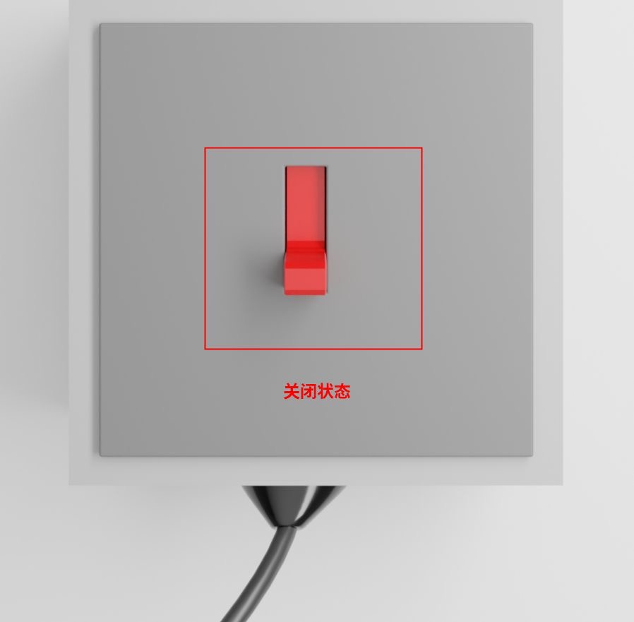
Before connecting the power cable, please ensure it is turned off to guarantee safety during the connection process. Only professional electricians or qualified personnel should perform the following operations.
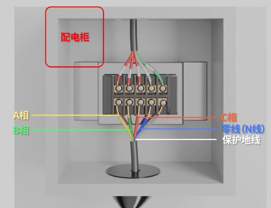
First, turn off the switch on the power supply. Then, connect the one-to-five power cords to the device in the following order from left to right: Phase A, Phase B, Phase C, Neutral wire (N), and Protective Earth wire (PE).
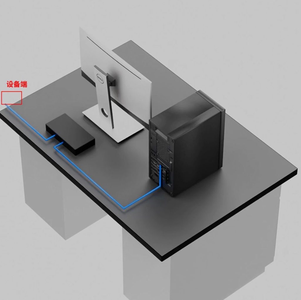
Connect the Ethernet cable directly to the computer, or use an Ethernet switch if multiple testers are involved.
3. Turn on the tester
After finishing the wiring of the device, turn on the red power switch located at the bottom rear of the unit. If the device does not start (and the screen remains blank) after switching it on, please check whether the emergency stop button on the front has been reset.
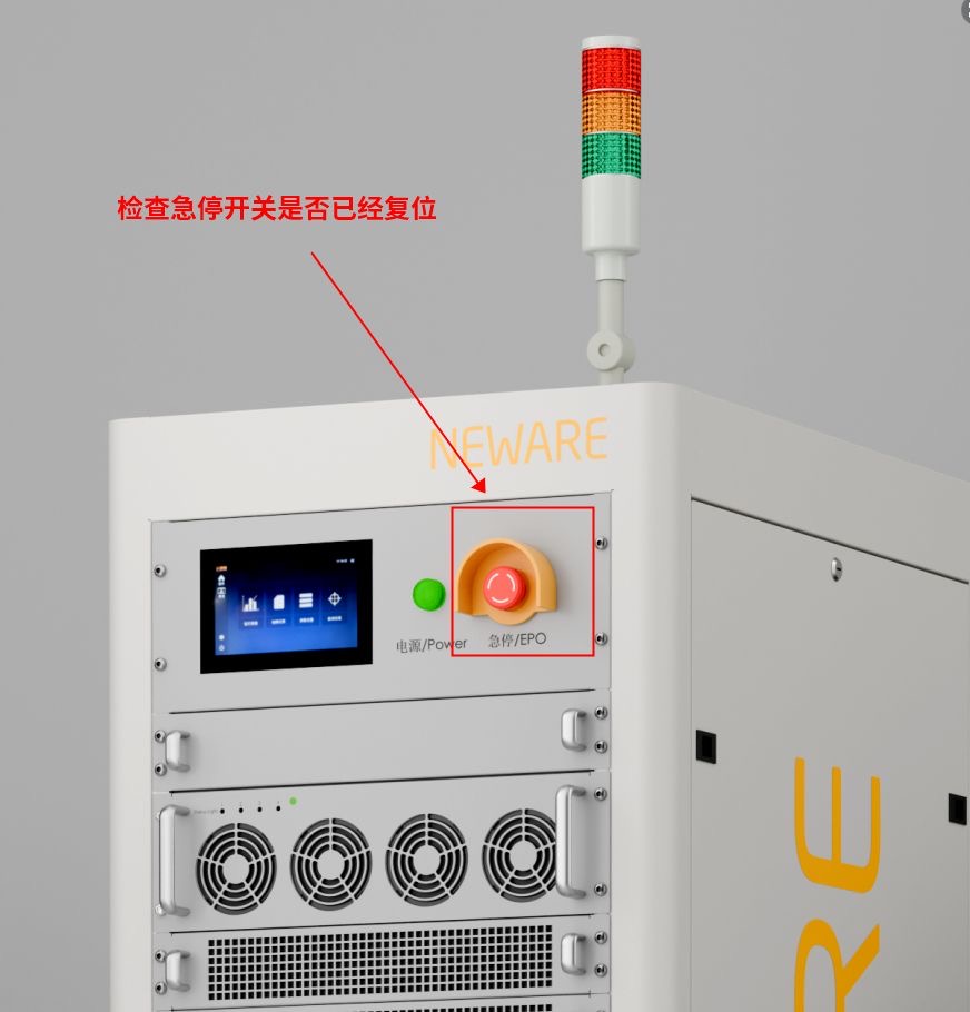
Turn the stop button clockwise to reset it, then repeat the previous step.
4. Ethernet setting
4.1 Check Device IP address
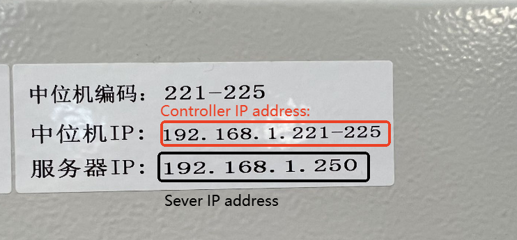
You can find the device’s IP address on the sticker. Note that some devices may contain multiple controller units.
Take note of the the Server IP address, as it will be needed in a later stage.
4.2 Set up Ethernet IP address
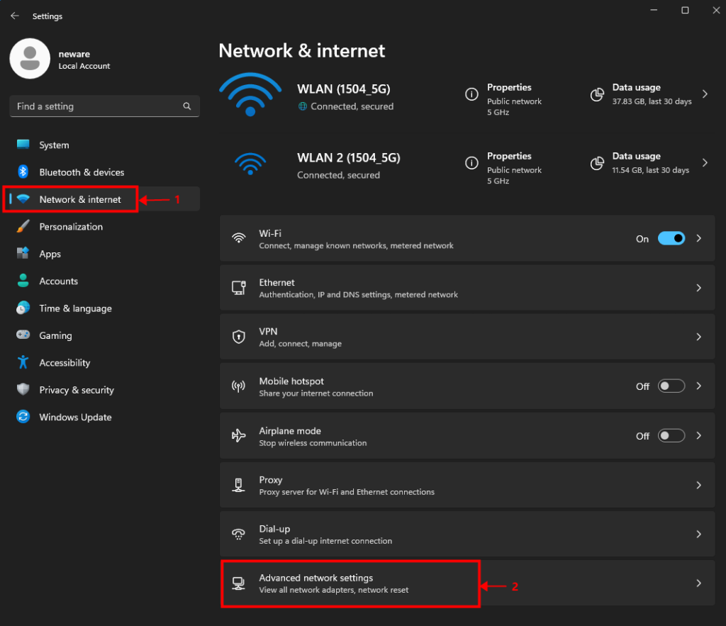
【Settings】 >【 Network & Internet】 >【 Advance network settings】
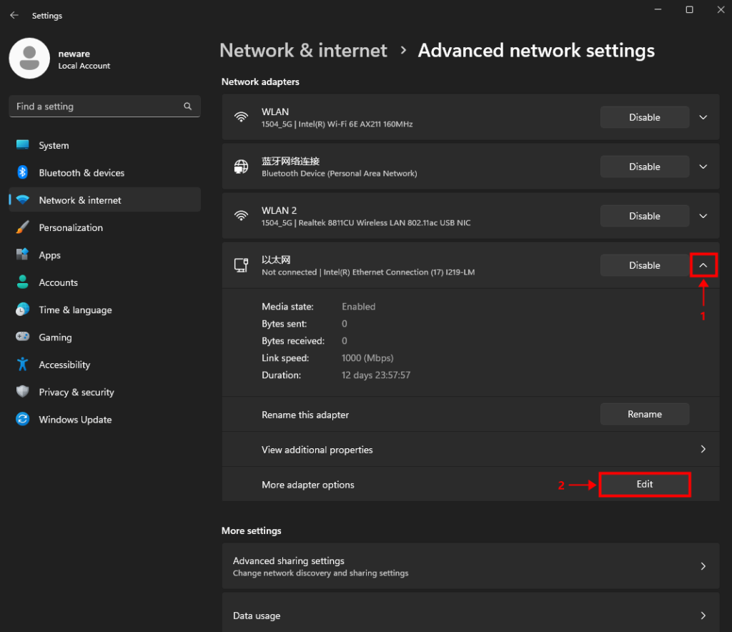
Find the ethernet block, expand hidden options, and select 【more adapter options】.
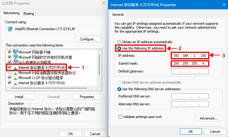
Double-click on the TCP/IPv4 setting.
Select the second option and type in the IP address manually.
Type in the Server IP address shown on the sticker at the front of the tester.
5. Software download and installation
Download link: BTS 8.0.1 (64 bit)
Other software options: https://www.newarebts.net/download/
6. Software set up
6.1 Log in
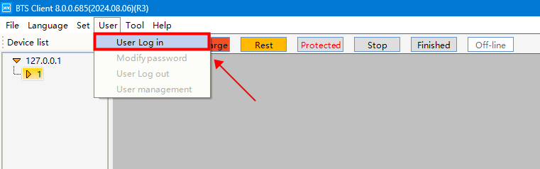
【User】 >【 User Log in】
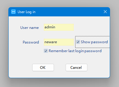
User name: admin
Password: neware
Recommended steps (not mandatory).
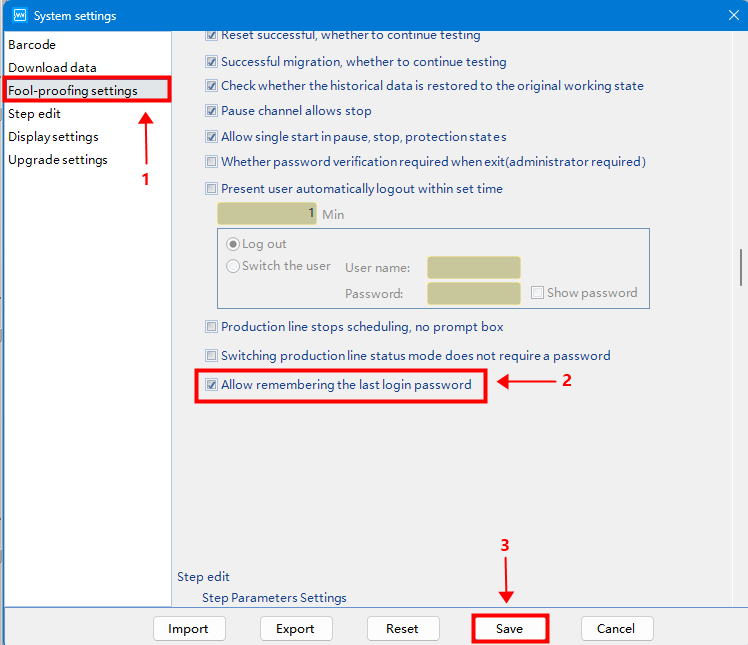
Allow remembering the password to avoid entering it each time you adjust the settings.
6.2 Reset mapping
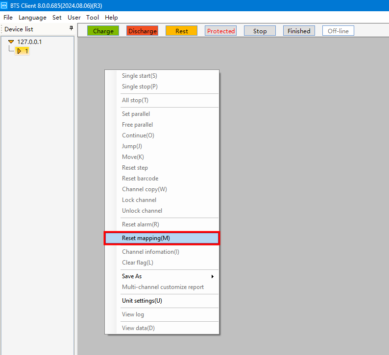
Right-click and select 【reset mapping】.
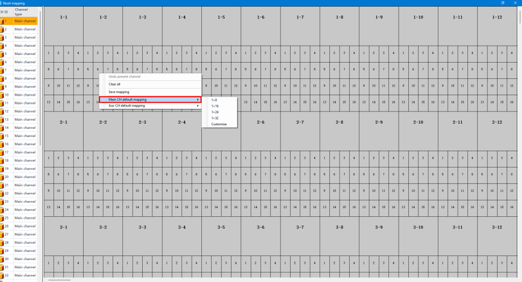
Right-click and select 【main CH default mapping】. Choose your preferred layout.
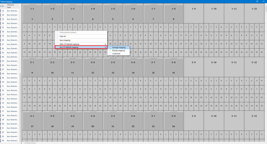
If you have auxiliary channels (for extra voltage and temperature measurements), drag them under the related main channels, or use average mapping to assign them to the main channels.
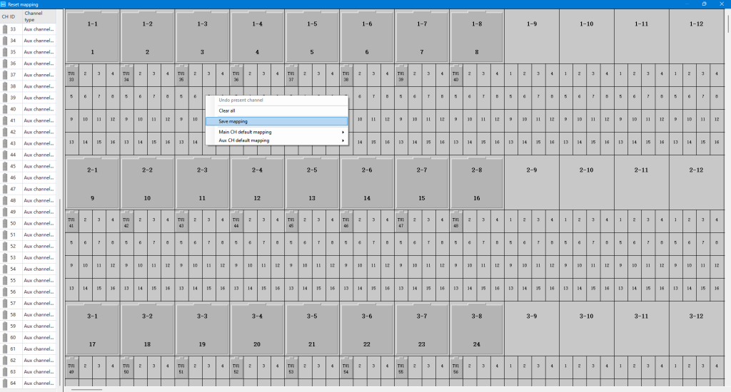
Save mapping before you close down this window.
6.3 Adjust the display to fit your screen and application
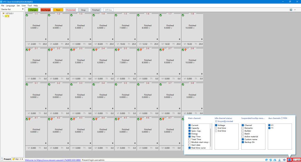
Adjust the display settings at the bottom of the page to fit your preferences.
6.4 Start a test
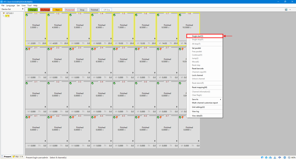
Choose the channel(s) for testing, right-click, and select 【Single start(s)】.